Flash trigger
My first electronics project was a flash trigger for high-speed photography. This circuit is based on a similar design by Johannes Eriksson.
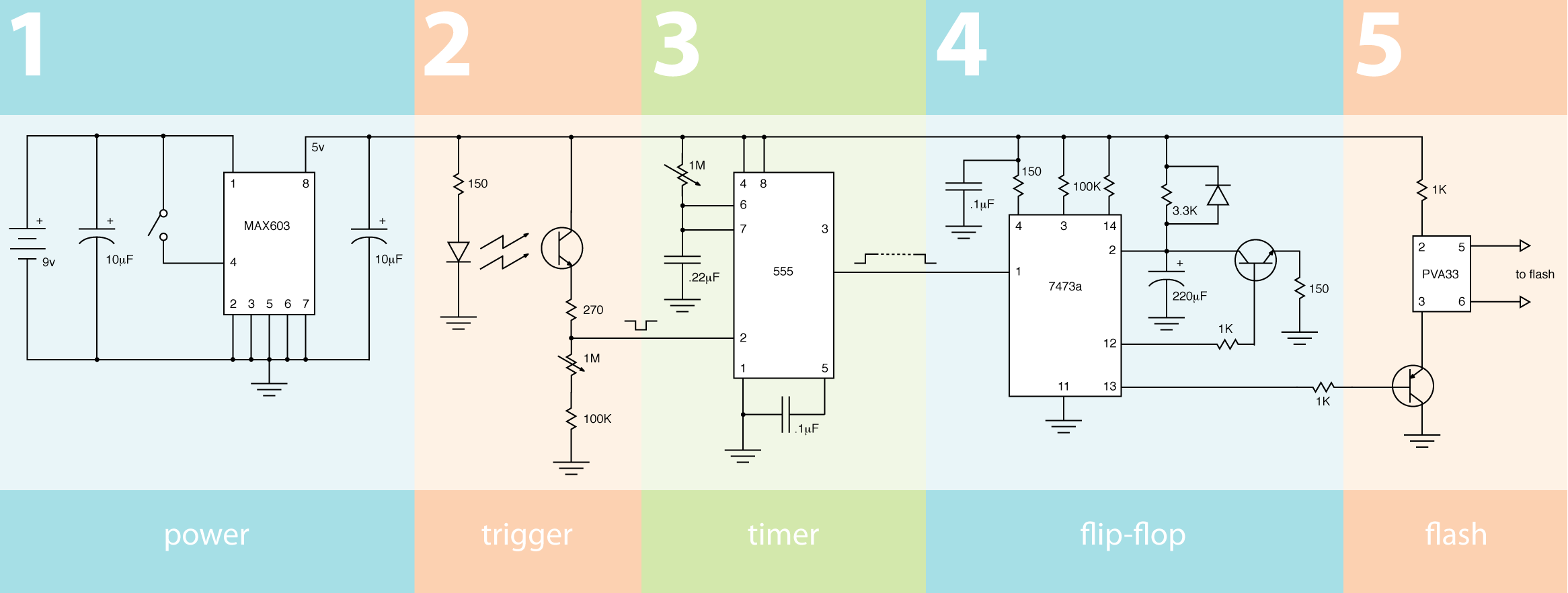
Like Eriksson's, the heart of my flash trigger is a 555 timer and a flip-flop. The timer lets us adjust the delay between the trigger and the flash — useful when we want a falling drop to fall a few more inches before we capture the photo.
Power supply
A MAX603 linear regulator provides a stable 5V power supply from a wide range of input voltages.
Trigger
The trigger circuit uses an infrared LED and a phototransistor to output a change in voltage when the light beam is interrupted. Fairchild Semiconductor has a good application note about phototransistors — these useful devices allow current to flow only when light is present. A large resistor between the phototransistor and ground causes 5V to be output when light is present and pulls the output to ground when the beam is interrupted.
Unfortunately, ambient light will hit the phototransistor even when the LED beam is interrupted. For example, the phototransistor may only reduce the voltage at its output by 1V when the beam is interrupted — it normally outputs 5V, and the 555 timer won't trigger until the voltage dips below 1.67V, so the change in voltage won't be noticed.
To mitigate this, we divert some of the current from the output of the phototransistor to ground with a variable resistor — this subtracts voltage from the circuit's output. We adjust the variable resistor until the trigger circuit only outputs 2V. When the beam is interrupted, the 1V drop in voltage will reduce the phototransistor output to 1V and trigger the 555.
Timer
The output from the trigger circuit is connected to the 555 timer's trigger input. When the output from the trigger circuit goes low, the 555 puts 5V on pin 3 and begins to charge the .22uF capacitor on the left. The resistor and capacitor on the left form an RC circuit — the lower the resistance of the variable resistor, the faster the capacitor charges. When the capacitor is nearly full, the 555 drops pin 3 back to ground.
Since the variable resistor controls how long the 555 timer's output stays high, we use it to control the delay between the light beam trigger and the flash. In order to do so, we need a component which will wait for the 555 output to go from ground to 5V and back to ground again — and that's our flip-flop.
Flip-flop
The flip-flop has two inputs (pins 3 and 14), two outputs (12 and 13), and a clock input (1). Each time the clock input goes to 5V and then back to ground, the outputs change state. The outputs are always opposites — if one is at 5V, the other is at ground. The flip-flop is wired so that the outputs toggle back and forth each time the clock input is pulsed.
Pin 2 of the flip-flop is a reset pin — when it is connected to ground, the chip resets its outputs so that pin 12 is at ground and pin 13 is at 5V. The resistor and capacitor connected to the reset pin form an RC circuit, like the one connected to the 555 timer; when power is applied, the pin will start out at ground and gradually rise to 5V as the capacitor charges. This resets the flip-flop to a known state when the circuit is powered on.
After the flip-flop has been reset, it waits for a pulse on pin 1. It triggers on the falling edge of this pulse — not when it goes from ground to 5V, but when it falls from 5V back to ground. This corresponds with the end of the 555 timer delay. This causes the outputs to invert — pin 12 will go from ground to 5V, and pin 13 will go from 5V to ground.
Each output is connected to the base of a transistor: an NPN transistor at pin 12, and a PNP transistor at pin 13. An NPN transistor allows current to flow when voltage is present at its base. Likewise, a PNP transistor allows current to flow when its base is at ground. The transistors act like switches in our circuit — they are normally off but conduct current when the flip-flop is "flipped" by the 555.
To recap: when powers is applied, the flip-flop outputs are reset. Pin 12 is at ground and pin 13 is at 5V — so both transistors act like open switches. At the end of a pulse from the 555, the output pins invert and both transistors turn on.
Flash
The PNP transistor is connected to a PVA33N solid-state relay. This is a special type of switch which allows a large voltage (the flash) to be controlled by a much smaller voltage. Internally it works much like our light trigger — pins 2 and 3 of the PVA33 are connected to an LED inside the case. When current flows between these pins, the LED activates a phototransistor and allows current to flow between pins 5 and 6.
Conveniently, flash units fire when their pins are connected together. If we connect a flash hotshoe to the PVA33, the flash will fire when the flip-flop changes state.
The circuit should reset after firing the flash so that it can be triggered again. Recall that we can reset the flip-flop by pulling pin 2 to ground. The NPN transistor at pin 12 controls another RC circuit, discharging the 220uF capacitor over a period of time while the flash fires. When the capacitor is fully dischanged, the flip-flop resets itself and both transistors turn off.
Putting it all together
The phototransistor in our light trigger is normally lit up by the LED, so it conducts 5V to the 555 timer's trigger input. When the light beam is broken, it stops conducting current and the trigger input voltage goes low.
When the 555 sees a low voltage at its trigger input, it puts 5V on pin 3 and the .22uF capacitor begins to charge at a rate determined by the variable resistor above it. When the capacitor is charged, the 555 brings pin 3 back to ground.
When the 555 output goes from low to high and back to low again, the flip-flop inverts the state of pins 12 and 13. This activates both transistors — one fires the flash by allowing current to flow through the PVA33 relay, the other bleeds current out of the capacitor connected to the flip-flop's reset pin. When this capacitor has discharged, the flip-flop resets and the transistors turn off.


